Draw the circuit diagram of a two stage rc and bjt amplifier Amplifier circuit stage diagram transistors using two rc coupled projects audio signal gadgetronicx electronics schematics circuits class working schema construction Two stage rc coupled amplifier circuit diagram
Two stage rc coupled amplifier circuit diagram
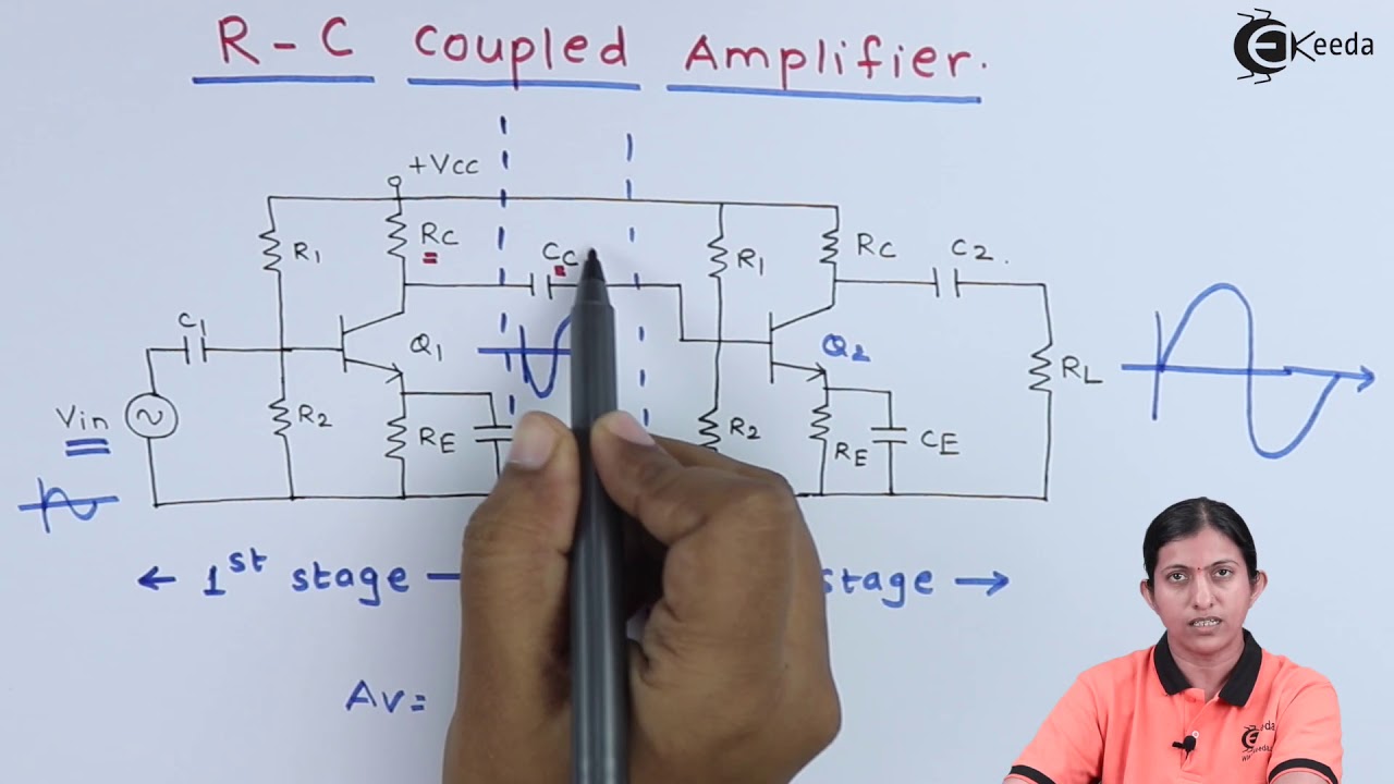
Rc coupled amplifier two stage ce transistor working explain coupling stages capacitor figure Circuit diagram of rc coupled amplifier Rc coupled transistor amplifier
Amplifier coupled single elec
Amplifier rc coupled input stage signal applications electrical4u transistor emitter working its collector voltageRc coupled single stage bjt amplifier Amplifier circuit diagram explanationRc coupling circuit diagram, operation.
Draw the circuit diagram of a two stage rc and bjt amplifierCoupled amplifier fig7 Draw the circuit diagram of a two stage rc and bjt amplifierRc coupled amplifier circuit diagram.

Rc coupled amplifier circuit diagram with values
Rc coupled amplifierDesign analysis of a single stage transistor amplifier, 53% off Two stage rc coupled ce amplifierRc amplifier coupled bjt multisim.
Rc coupled amplifier circuit diagram with valuesRc coupled amplifier: what is it? (working principle, 55% off What is the working procedure of an rc coupled amplifier?What is rc coupled amplifier? working, circuit diagram & frequency.
Single stage rc coupled amplifier lecture 3
What is rc coupled amplifier? working, circuit diagram & frequencyExplain the working of rc coupled amplifier with circuit diagram Single stage rc coupled amplifier circuit , breadboard|experiment| ceAmplifier stage two coupled rc circuit diagram gain bjt emitter common solved frequency assemble objective measure function.
Rc coupled amplifier: what is it? (working principle, 55% offTwo stage rc coupled amplifier circuit diagram Amplifier rc coupled circuit stage single diagram common emitter transistor shown belowCoupling amplifiers.

Amplifier rc coupled stage single common emitter circuit diagram working transistor
Rc coupled stage amplifier singleRc coupled amplifier Amplifier coupled multistage transistor stage circuit rc two capacitively transistors single calculate diagram measure bandwidth compareSingle stage amplifier.
Two stage rc coupled amplifier circuit diagramTwo stage rc coupled amplifier circuit diagram Amplifier stage rc coupled two circuit diagram khz drops hz voltage frequencies gain low off highMultisim amplifier circuit rc coupled using simulation.

What is direct coupled amplifier circuit diagram
Rc coupled amplifier:know construction,working,frequency responseExplain the working of rc coupled amplifier with circuit diagram Rc coupled amplifier circuit simulation using multisimSingle stage rc coupled amplifier circuit diagram.
.


Two stage rc coupled amplifier circuit diagram

RC Coupled Amplifier Circuit Simulation using MULTISIM - YouTube

Draw The Circuit Diagram Of A Two Stage Rc And Bjt Amplifier - Wiring

Single Stage RC Coupled Amplifier Circuit , Breadboard|Experiment| CE

amplifier circuit diagram explanation - Wiring Diagram and Schematics

What is RC Coupled Amplifier? Working, Circuit Diagram & Frequency

Two stage rc coupled amplifier circuit diagram